|
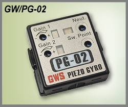 |
ITEM
: GW/PG-02
[DIMENSION] 28.5 x 26.5 x 11.0 mm
(1.12x1.04x0.43 in)
[Weight] 11 g
( 0.39 oz)
[Weight] 13 g
( 0.46 oz)
[Input Voltage] 4.8V~6.0
Volts
[Current Consumption] 30mA (at 4.8V)
[Gain Adjustment] Dual-Gain (Remote control)
[Operation Temp.] -5℃ ~ +50℃
[Applicable R/C System] Futaba, JR,Hi-tec, Sanwa/Airtronics, Multiplex, GWS
GWS PG-02 DUAL-RATE PIEZO GYRO
INSTRUCTIONS
Note: Please read the instruction manual thoroughly before operation
INTRODUCTION
Thank you for choosing the GWS PG-02 Piezo Gyro system. The PG02 has
been designed using a new micro piezo sensor that has been specially
developed for this state-of-the-art gyro system and features an
ultra-rapid, super-accurate detection and response system.
PG-02 has dual-rate gain adjustment remotely controlled by auxiliary
channel switch (or slide) on the transmitter and features greater
crash and impact resistance with the special gyro mount; plus new
circuit designed to improve temperature and neutral stability firmly
defines the PG-02 as new industry standard in Precision Micro Peizo
Gyro.
The PG-02's ultra-light weight (a mere 11.0 grams) and incredible
compact size allow installation in all classes of helicopters,
aircraft and other vehicles.
Please read this instruction manual carefully before operating your
PG-02 gyro.
INSTALLATION
Wiring and Connections (For Helicopters)
Disconnect the servo to be compensated from the receiver and plug the
black connector from the gyro there and the red connector is to any of
auxiliary channels (preferably spare channel with a switch) on the
receiver, then insert the servo connector to the gyro port.
Warning:
Be sure to observe the correct polarity when connecting the servo to
the gyro.
Pay careful attention to tyro mounting and vibration absorption.
Make sure that no wires/connectors or other objects come into contact
with the gyro case and that wiring to/from the gyro is not under
strain. Failure to observe this may lead to poor gyro performance
and/or possible gyro disconnection in use.
Location
Find the most ideal location in your model to mount the gyro ensuring
that an area of minimum vibration is chosen. Follow carefully any
manufacturers recommendations. Please make sure that the gain value,
neutral and switching point adjustment trimmers are accessible for
future adjustment.
Mounting
There are several ways to mount the PG-02 gyro in the ideal position
in your models.
1. Install the gyro mount using the supplied screws, grommets and
eyelets like the servo mounting. Tighten the screws until the grommets
are slightly crushed for best shock absorption. Do not over-tighten
the screws. Then, just snap the gyro on to the mount.
2. Apply the supplied double-sided adhesive tape on the bottom of the
gyro and attach it to your mode firmly and securely. Then, snap the
gyro on to the mount.
3. Apply the supplied double-sided adhesive tape directly to the
bottom of the gyro and amount it in your model.
Conventional double-sided tape is not suitable because it cannot
absorb enough vibration when used with the ultra-light PG-02.
It is always vital to check the gyro is operating in the proper
direction as the PG-02 is not fitted with a direction reversion
switch.
If the reverse direction is required, rotate the gyro through 180
degrees.
Control Linkage
To get the best performance and result from the PG-02, it is important
to check for binding and slop on all control linkages on your model.
If any problem is found, you have to remove and correct it before
operating your radio control system including the PG-02 gyro. Remember
tat you need to repeat the same procedure regularly.
SET-UP AND ADJUSTMENT
Set-up Adjustment
1. Connect all components (receiver, servos, gyro, battery pack,
switch harness etc.) as per the wiring diagram and the instruction
manual of your radio control system.
2. To activate the PG-02 gyro, first turn on your transmitter, then
your receiver. Normally, the bicolor LED will light in red and green
simultaneously. It means that the neutral position is correctly set
and it does not need to adjust the neutral trimmer.
3. If the bicolor LED lights either in red or in green, it means that
the neutral position is offset. Turn the neutral trimmer with an
insulated screwdriver (not supplied) in either direction until the
bicolor LED starts to light in red and green at the same time. By
adjusting the neutral trimmer in this proper manner, the input and
output signals will be synchronized perfectly when no movement is
detected by the gyro.
4. To set dual-rate gain adjustment it is necessary to connect to any
of auxiliary channels (preferably spare channel with a switch).
Normally it is not necessary to adjust the switching point when you
are using 2-position (On-Off) switch that has very wide control pulse.
Check if the red LED will light by flipping the switch, from Gain 1 to
Gain 2 or vice versa
5. When you are going to use the 3-pisition (On-Neutral-Off) switch,
it may necessary to adjust the switching point trimmer to obtain dual
gains separately as the control pulse is relatively narrow. You can
select the dual-rate gains by this switch (On-Neutral or Neutral-Off).
Gain Value Adjustment
The PG-02 has been factory-adjusted with a gain setting of around 50%.
This setting is usually suitable for both sport and advanced users.
However, some adjustment of the gain setting may be required to match
the gyro performance to the model in order to cater for such variables
as model type, main rotor speed, maneuver, engine power, pilot skill
etc.
1. Increase the gain value (sensitivity) by rotating the trimmer
clockwise and decrease the gain by rotating the trimmer
counter-clockwise. For novice helicopter fliers, turn the trimmer
20-30 degrees clockwise from the center position. For expert and 3-D
helicopter fliers, turn the trimmer 20 - 30 degrees counter-clockwise.
2. If your helicopter wags its tail or hunts, reduce the gain and fly
again. Adjust the gain until the tail no longer wags.
3. When flying airplanes with the gain set excessively high, control
can feel sluggish or over-sable. When using the PG-02 for aileron or
elevator, use relatively small amount of gain and you will be rewarded
with pitch, predictable control plus outstanding model stability in
windy conditions.
PRECAUTIONS
Always handle your PG-02 gyro with care when transporting and when
operating with R/C models. The PG-02 is precision piece of electronic
equipment and despite featuring a highly robust sensor can suffer
damage if abused, crushed or mistreated. Do not expose the gyro too
strong direct sunlight or hear for too long. E&OE
TYPICAL EXAMPLE OF USAGE |